Funny enough, in the last post I forgot to describe an important component. When shaping audio signals, it’s vital to be able to actually amplify sound. This can be achieved with transistors. In a schematic, they look like this:

You might recognize these little fuckers from their boring role in computers, where they are used as switches between 0 or 1, off or on. But in audio they make volume go up, and quite linearly so, as I understand it. There is battery-level voltage applied at the collector (C). The audio signal enters the base (B). The voltage from C gets modified by the B voltage and escapes the emitter at its new amplitude (E). When you apply 9 volts at C, while your audio signal just oscillates in the area of millivolts, the resulting wave is of way higher amplitude, but still has the shape of that original audio signal.
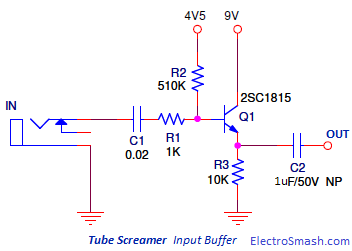
Here you can see the input stage of a TubeScreamer, with Q1 being the transistor. Guitar signal goes in on the left; 9V is injected into the collector from the top; stuff goes out at the bottom and rushes towards OUT.

I left the realm of clumsy cable constructions and did my first circuits on a breadboard. Meanwhile I fried 2 red LEDs. I think the first one died because of a somehow missing resistor. The second one because I forgot that you measure current in series and created a bridge around a resistor with my multimeter 🤷♀️ – Anyway, here you see some LEDs. Current flows each time I push the button. The green one signifies the capacitor being loaded (it’s in series before it). The red one (yeah, I bought some new ones) is lit by the energy saved by the capacitor each time the switch closes the second circuit. Unfortunately, I was dumb enough to push the button roughly in rhythm with the music. Now everything happens too fast and it’s not as instructing as it could be.
I also built some simple sound circuits, where voltage moves a piezo ‘speaker’. This was so unimpressive that I didn’t even take a picture.
Apart from that I tried to read some pedal circuits before sleeping. I had a small revelation when I stumbled upon the clipping stage of an MXR Distortion +, which is about as simple as it gets:

I couldn’t quite understand it. My thoughts were somewhat along the lines: “This is weird. Those diodes are placed somewhere where there’s not a lot of resistance, but all the beautiful power goes down the drain [earth]! How does it even get there, doesn’t it just wanna flow towards the exit, when RV-OUTPUT is wide open and there’s no resistance there at all?!” WRONG. Turns out, I thought too linearly. Kind of: Energy goes in at IN and out at OUT or maybe, if it wants, elsewhere. Rather like programming, input-output, it’s that simple. But in electronics I guess you have to think a lot more relational. What happens in the diode-equipped part that goes to ground, influences nonetheless what happens at OUT. You can’t see it as absolute.
For certain waves, on the upper or lower cycle of the AC, D1 and D2 are permeable and without resistance. That means, that part of the signal then enters this area and goes to ground, while the rest moves towards OUT and forms our new signal. We don’t force current through the diodes (as is the case in other circuits), but we steal some parts of waves and trash them, which shapes the remaining waves via difference. Likewise with the capacitor. As we learned in the last post, capacitors let higher frequencies pass along easier than bass frequencies. This way higher frequencies rather take the path into the ground. Thereby extreme treble harmonics in the now-distorted waveform get shaved off.
Another realization was the constant confrontation with the fact, that we always have two different circuits in a pedal. For one, we have the AC from the guitar pickup, at mV scale. Then we have the 9V circuit from the pedal (battery or power supply). That’s why a lot of circuits have some measures of blocking DC (via capacitors) or why you bias the current of a transistor by e.g. 4.5 volts: To give it enough operating space to operate with its DC on the audio wave’s AC. Both circuits only touch each other in active components, like aforementioned transistors. Both use the same ground.
I hope I can show you my first pedal circuit next time. I will build a very simple fuzz circuit. I’ve already got the parts. Stay tuned.