I’m gonna paint my mental picture of the matter so far. I’m a total beginner, so feel free to mail me if I got something wrong.
When you hit the string of an electric guitar metal vibrates over a magnetic pickup. The magnet acts as an inductor and the electrons in the guitar’s wiring start to move. This wave, current, moves towards the cable and makes its way through the pedals. Later it hits the amplifier and is converted into mechanical energy by the speaker. The result meets our ears. As I understand it, the electrons themselves don’t bother to move far, just across neighbor atoms. It’s the collective small steps that create a big wave, and for once the result is quite wholesome. The potential to make those waves is called voltage.
Circuits
When electricity happens, there’s a circuit. This is the case with the guitar and the pedals as well. – “What, a circuit, that sounded pretty much like a line or something!” – Well, like us humans, electricity has a tendency to return to earth. This is called ground, or earth. An electric guitar seems to be grounded through the cable. Pedal circuits on the other hand are grounded by their connection to the negative pole of the battery or the negative pole of the power adaptor. This ground has to exist for electricity to occur.
The sounds coming out of the guitar consist of alternating current (AC) – the string moves left and right, after all – but guitar pedals are powered by direct current (DC). This means we inject DC into the pedal circuit to modify an AC signal – make the sound louder, distort it, whatever, basically manipulate the ‘sound wave’. As I understand it, earth acts as a kind of zero calibration for this whole circuit. As the voltage which drives the current is difference, you need something to differ from. The positive pole of the battery does differ by 9V from ground, or something like that.
All the tasks pedal circuits perform deal with manipulating those differences. The following paragraphs summarize my understanding of the most important components for audio signal manipulation.
Resistors
Current likes to take the easiest path. If there’s resistance, current says: I would prefer not to. You can use resistors to scare current away. Move on, nasty current! You can direct or split voltage this way. Only a little resistance, some current might actually take that path and voltage is divided accordingly. Crazy resistance, no way.
A famous example for a resistor in an audio circuit would be a volume potentiometer. The potentiometer does some wiping when you rotate it and a resistor changes its resistance in the process. If there’s shitloads of resistance, the current is not in the mood to move on towards the output of the circuit. Where does it go then? I don’t know yet. Maybe into the ground? Or maybe it gets converted into heat, like in a normal resistor? – But if the potentiometer is turned up all the way and there’s little resistance, current is cool with moving on to the next pedal.
Diodes
Franzi tried to sell me the idea that diodes are kind of a one way street. Imagine you build a complicated network of different voltages with resistors in all sorts of places. Some current might be tempted to move backwards. We don’t want that. A diode seems to allow current to flow only one way.
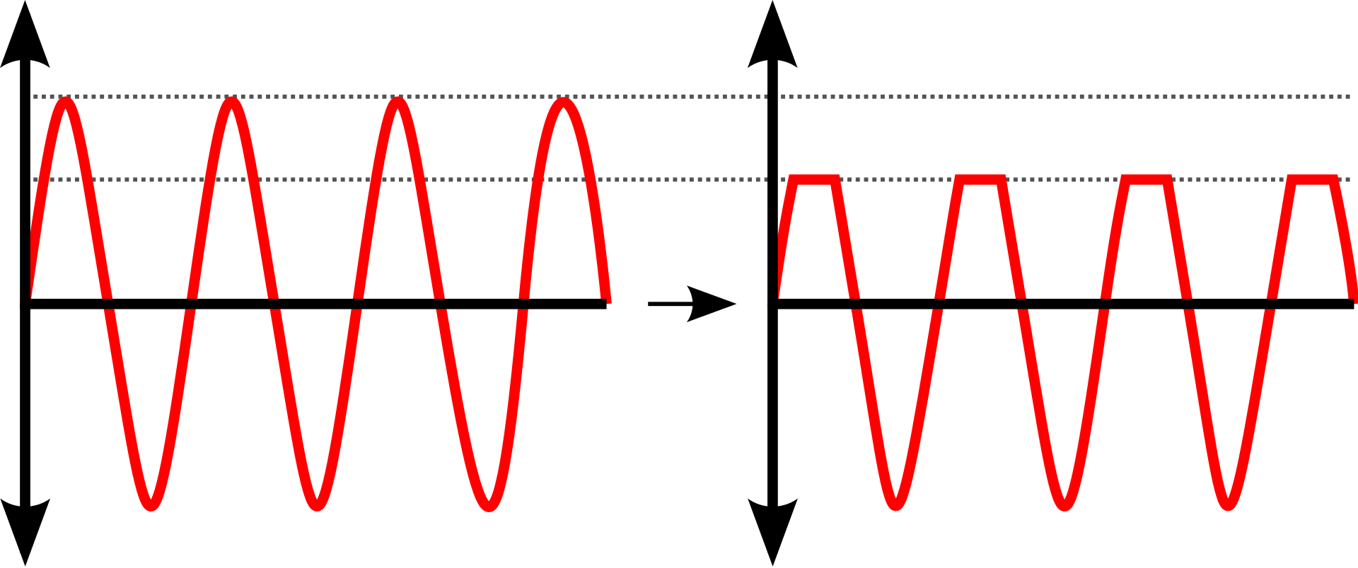
Now, in pedals, diodes are usually utilized for clipping == distorting a signal. It seems you can take advantage of the fact that diodes only become restrictive when a certain threshold is passed. Remember, our guitar signal is AC, but we’re in a DC circuit in our pedal. We feed the guitar signal into a diode which via its direction likes to block positive voltage. This only happens after a certain threshold is passed, so a portion of the positive voltage gets through, the rest gets clipped. This sounds fucked up, as in pleasurably fucked up. Here’s an illustration:

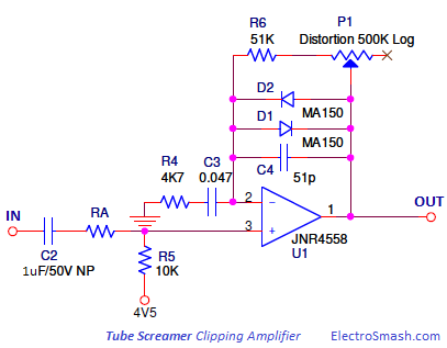
For ‘traditional’ Overdrives we don’t want to clip only one half of the waveform. Here’s the clipping circuit of a TubeScreamer. There are 2 parallel wired diodes (D1 & D2) to clip the positive as well as the negative voltage cycles of the AC, respectively.

The diode challenge from Franzi’s starter kit somehow didn’t work, it involved rotating the motor to load a capacitor (see below) by hand and prevent current from flowing back with the diode. But I completed the experiments with the other kind of diodes in the kit, LEDs. I can confirm they really don’t work if installed the wrong way round. Diodes have a resistance of their own, so it seems, and while regular diodes resist via converting current to heat, LEDs create light, as you might know.
Capacitors
Capacitors have the ability to store electrical energy for a while. If you feed them, they charge. If you connect them to another circuit, they release their storage into this circuit. If you put a resistor behind them, it regulates the speed of the discharge. Higher resistance means: Saved current isn’t that eager to travel on and likes to take baby steps. Lower resistance means: Current is flowing towards the exit like a crazy person. Gonna show you a video where I charge a capacitor through a circuit with a green LED and then discharge it into a circuit containing a red LED. Franzi says, if you choose a larger resistor the light would be less bright but shine on longer. I like my lights bright.
While resistors are used to control the amplitude of the signal and diodes are used to manipulate the shape of the signal, capacitors mess with the frequency of the signal. While it might be obvious that they seem to fuck around with the time domain somehow, the exact ongoings were rather not intuitive for me. Big thanks to Flo for giving me a good explanation.
Charging a capacitor means hitting it with positive voltage. Discharging means hitting it with negative voltage. AC (our signal) has positive and negative voltage cycles. So if some current with negative voltage hits the capacitor this means the capacitor gets discharged immediately. As I understand it, the current just continues to do its thing, whereas a ton of DC actually breaks the circuit because the capacitor sucks up all it can and then has no way to release it again. As Flo phrased it, capacitors simply break the circuit for DC while they let AC pass somehow.
Now you have to remember that low notes have way larger cycles in the signal (they’re called low frequencies after all), so they don’t change as often from positive to negative as high notes (== high frequencies) might. This means, a capacitor has higher resistance to low frequencies, letting higher frequencies pass easier, thereby filtering the tone 🤯. At least in principle, exact workings seem to be dependent on the properties of the respective capacitor.
New Items From Franzi
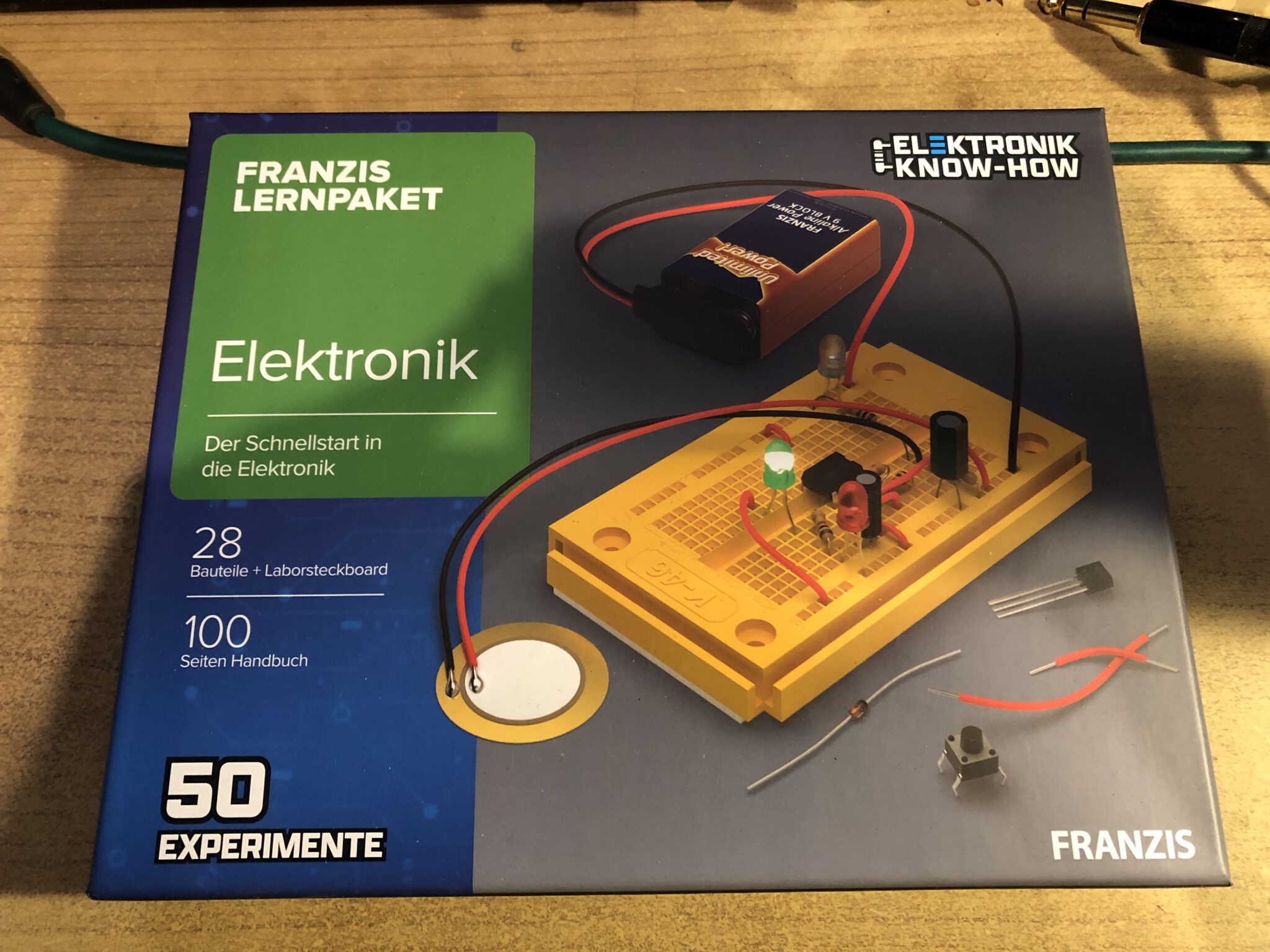
As I’m almost done with the starter kit, I bought two more kits from Franzis. The first one is an electronics kit coming with a breadboard. I expect it to be the sequel to my starter kit. The second one is for learning how to solder.


I was pleased to learn that the stuff you solder components together with is literally called “Das Lot” in German. So I recorded a little song called “Das Lot” to glorify solder. I’d like to join JHS Pedals’ tradition of short demo snippets and this shall be the first entry.
Edits
03/27/2022: Differentiate voltage & current